Replacing backlight with LEDs in Raymarine E-Series E120 display

Anastasia
Phil May and Andrea Twigg
Wed 31 Oct 2018 16:28
|
It is a well known issue with Raymarine MFDs that the fluorescent tube
(CCFL) backlight fails over time. More modern displays use LEDs as
backlighting, which is simpler and cheaper to install, and quite simple as a DIY
project. Here is a description of how I retro-fitted LED backlights to my
Raymarine display.
The general approach for controlling LED strips is described here: https://learn.adafruit.com/rgb-led-strips/usage
We are going to intercept an existing signal in the display, which is there
to control the brightness of the fluorescent tubes, and use this to control the
brightness of the LEDs. The signal is already pulse width modulated (PWM)
so we can feed it directly into a transistor (MOSFET) to control the LEDS.
- 5m of LED light strip. I purchased 5m of 12V cool white 5050 SMD
LEDs off eBay. The non-waterproof ones are fine.
- An N channel MOSFET. Any high power MOSFET will do. Adafruit
suggests the IRLB8721. (I had a BUK455 lying around so I used
that.)
1. Remove the plastic bezel from your display. Do this with your
fingers not a screwdriver. You will find that by twisting the sides of the
bezel a little you can unclip it without damage.
2. Unscrew all the small screws you see on the front panel (including the
one that “voids the warranty”!). Remove the front panel, being careful
with the seal, which you want to remain waterproof when you reassemble.
3. Undo the ribbon cable attached to the keyboard circuit board and gently
release the three white clips that hold it in place, allowing you to remove the
board completely. Take care with the ribbon cable. It releases by rotating
up the black clip from the BACK of the socket. The same applies to all the
ribbon cable connectors you will need to release.
  4. Remove the six long bolts that hold the display inside the case and
gently remove the display from the case.
5. Undo the ribbon connectors that run to the display screen, the two plugs
that power the CCFL lights, and also undo the single screw in the corner that
holds a ground wire. Separate the display from the circuit boards.
 The lights are just clipped in. Push the cable through the hole,
unclip the lights and discard them.
6. Turn the circuit board section over and you will see a white
reflective area. This is where you will be sticking the LEDs.
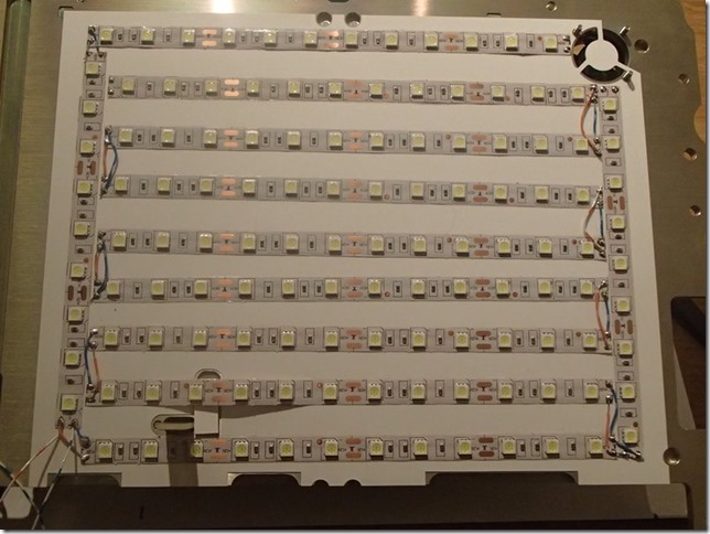
 Cut the leds into strips that fit on the white area. Make sure you
leave enough border that the LEDS will fit OK when reassembled. I used 126
LEDs, which is about 23 watts at full brightness, so similar power consumption
to the CCFL. Connect up the LEDs with wires to form a single strip (or strips in
parallel) You will find the LED tabs are surprisingly easy to
solder. Feed the LED power wires out through the same hole that once
carried the CCFL wiring. Clip the display back onto the circuit boards.
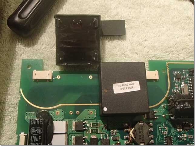
7. Remove both the high voltage transformers from the top circuit
board. These consume a fair amount of power even when disconnected from
the CCFL lights. I removed them by taking off the top circuit board,
inserting a flat head screwdriver by each pin and melting the solder to allow
the transformer to release a little bit at a time.
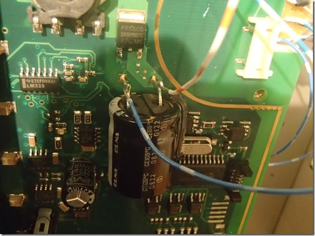
 8. Identify the power source for the leds. This is a big capacitor
near where you removed the transformers. (Note that this matches the input
voltage, so if you are using a 24V supply then you had better use 24V
LEDs!) After this mod your display will only work with a 12V supply (or
24V with 24V LEDs), but efficient voltage converters are cheap these days.
.
 Solder leads onto the legs of the capacitor. At this point you can
test your LEDs by hooking them up to these leads and turning on the
display. You should see the display at full brightness.
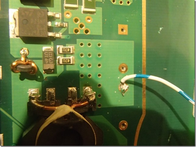
9 If this works then all that is left is to handle the dimming.
Identify the source of the PWM signal you are going to use and attach a
lead. This is one of the input pins to one of the transformers you
removed.
 10. Wire up the dimming circuit.
- The +ve lead from the capacitor(+12V) goes to the +ve on the LEDs.
- The –ve from the LEDs goes to the drain (middle leg) of the MOSFET
- The source (right hand leg) of the MOSFET goes to the –ve leg of the
capacitor (0V).
- The PWM signal goes to the gate (left hand leg) of the MOSFET.
11. Power up and test the dimming works. The dimming should work as
expected, except you will notice there is a “glitch” in the middle.
Apparently a known problem with this mod, documented on YouTube : https://www.youtube.com/watch?v=Bbu-aPysO4w
The PWM signal we are using traces back to a PIC microprocessor, so who knows
why the microcode in it is deciding to glitch. Live with it.
12. Reassemble, taking care to align all the gaskets correctly so it
remains watertight. Power up and run overnight at full brightness to check
it out.
|